
Gear and tools emblem, at 300 mm wide for a sign.
Download example SVG (5 kB)Download example DXF (124 kB)

Source image: Openclipart, ben, CC0 1.0.
A router cuts with a round bit, not a hairline beam. This page converts an image to a clean DXF in millimeters and covers the checks that matter for a router.
Each pair is an actual conversion of a public domain image, with the settings listed under it. You can download the exact files.
Gear and tools emblem, at 300 mm wide for a sign.
Download example SVG (5 kB)Download example DXF (124 kB)
Source image: Openclipart, ben, CC0 1.0.
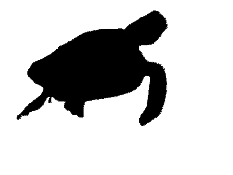
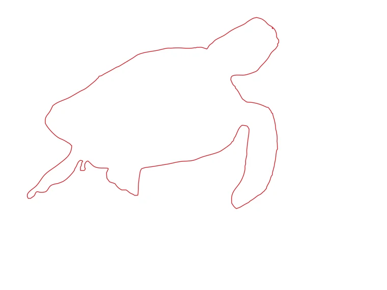
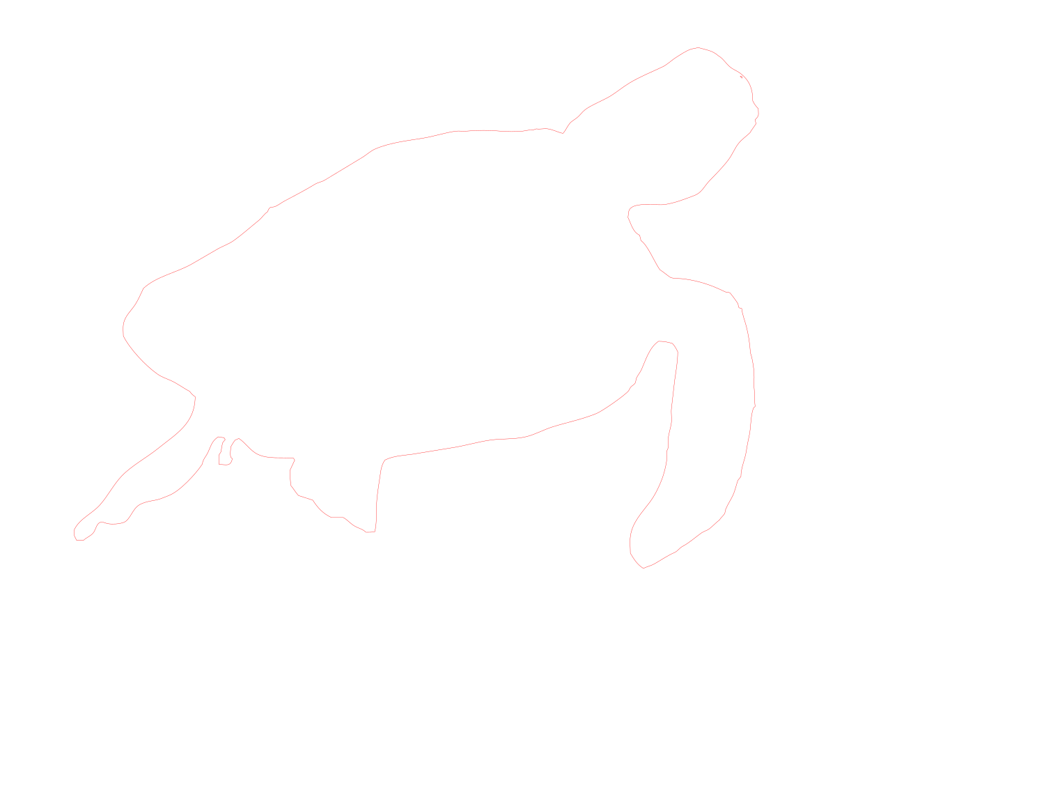
Sea turtle silhouette at 400 mm wide, a profile cut.
Download example SVG (6 kB)Download example DXF (93 kB)
Source image: Openclipart, dragonassbabe, CC0 1.0.

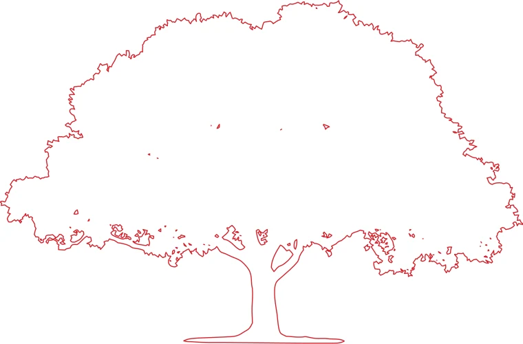
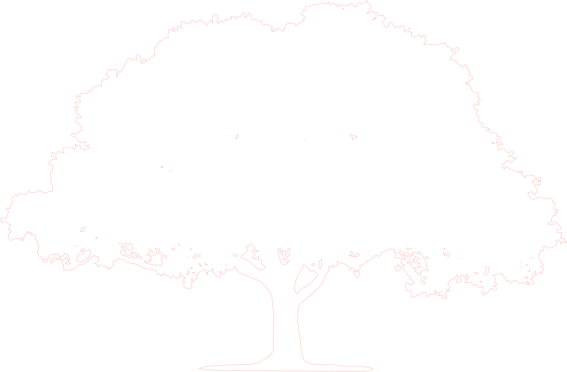
Oak tree silhouette at 500 mm wide.
Download example SVG (38 kB)Download example DXF (356 kB)
Source image: Openclipart, GDJ, CC0 1.0.
Free sample files, not watermarked.
We use the laser profile because it gives closed outlines in millimeters, which is what a CAM program wants.
A 3.175 mm (1/8 inch) bit cannot cut an inner corner sharper than its radius, and it cannot cut a slot narrower than its diameter. After you import the DXF, check the narrowest gaps and the sharpest inner corners against your bit.
The DXF is the exact outline. In your CAM software you decide whether the bit runs inside the line, outside it or on it. For a part you cut out, run outside the line so the part keeps its size. For a pocket, run inside.
When you cut a part free, it can move at the end and ruin the cut. Add tabs in the toolpath. They are a CAM setting, not part of the vector.
The DXF contains closed polylines, which is what pocket and profile toolpaths need. Open paths cannot be pocketed. The converter checks that every contour is closed when it writes the file.
No. It gives the exact outline. Tool offset is a toolpath setting.
No. It gives 2D outlines for profile and pocket cuts.
1500 mm wide.